Removing and Installing the Mirror

 Before removing the mirror from its cell, you need to verify that it is
mounted fully flush against the front lip of its cell. If it is not, you
need to carefully record the amount of gap between the mirror and its cell
at each of the three points where the Invar rods meet the cell. When
reinstalling the mirror, duplicating this gap will greatly ease collimation.
To check the gap, label each Invar rod so you know where the measurements
were taken. Carefully insert thin feeler gauges between the edge of the
mirror and the cell casting where it overhangs the mirror to intersect the
Invar rods. Start with the smallest gauge, usually .0015-inch, and work your
way up to larger sizes until you find the one that will not slip into the
gap. Back up one size and this is your mirror to cell gap at that point.
Once the clearances are logged, you can proceed with mirror removal.
Before removing the mirror from its cell, you need to verify that it is
mounted fully flush against the front lip of its cell. If it is not, you
need to carefully record the amount of gap between the mirror and its cell
at each of the three points where the Invar rods meet the cell. When
reinstalling the mirror, duplicating this gap will greatly ease collimation.
To check the gap, label each Invar rod so you know where the measurements
were taken. Carefully insert thin feeler gauges between the edge of the
mirror and the cell casting where it overhangs the mirror to intersect the
Invar rods. Start with the smallest gauge, usually .0015-inch, and work your
way up to larger sizes until you find the one that will not slip into the
gap. Back up one size and this is your mirror to cell gap at that point.
Once the clearances are logged, you can proceed with mirror removal.
 Once the cover is off, you will see which of three mounting methods hold the
mirror in place. The mirror is resting on the cast rim of its cell, perhaps
with several small cork spacers in the gap between the edge of the mirror
and the cell. If you are going to remove the mirror, you should mark the
position of the mirror and spacers so they can be put back in the same
place. Use an engraver to permanently etch an alignment mark near the edge
of the mirror. This mark should correspond with a permanent landmark feature
on the camera body such as the hinge on the film-loading door. This will aid
in reassembling the optics in the same orientation that they came from the
factory.
As previously mentioned, one scheme uses three springs to press the mirror
against the front face of the mirror cell. If this scheme is in your camera
it will be obvious as soon as you remove the first back cover screw. The
cover will begin to rise up by itself. Force the cover back down when
removing the rest of the screws to prevent damage to their threads. These
springs seat in three bosses cast into the rear cover. With the springs
removed, the mirror is loose and can be lifted out once the mirror
collimation hardware attached inside the rear of the tube is removed. A
variation of this method involves using the springs with a smooth-faced rear
cover. In this case, the springs are attached to the cover with RTV silicone
and the mirror may also be siliconed to the tube.
Once the cover is off, you will see which of three mounting methods hold the
mirror in place. The mirror is resting on the cast rim of its cell, perhaps
with several small cork spacers in the gap between the edge of the mirror
and the cell. If you are going to remove the mirror, you should mark the
position of the mirror and spacers so they can be put back in the same
place. Use an engraver to permanently etch an alignment mark near the edge
of the mirror. This mark should correspond with a permanent landmark feature
on the camera body such as the hinge on the film-loading door. This will aid
in reassembling the optics in the same orientation that they came from the
factory.
As previously mentioned, one scheme uses three springs to press the mirror
against the front face of the mirror cell. If this scheme is in your camera
it will be obvious as soon as you remove the first back cover screw. The
cover will begin to rise up by itself. Force the cover back down when
removing the rest of the screws to prevent damage to their threads. These
springs seat in three bosses cast into the rear cover. With the springs
removed, the mirror is loose and can be lifted out once the mirror
collimation hardware attached inside the rear of the tube is removed. A
variation of this method involves using the springs with a smooth-faced rear
cover. In this case, the springs are attached to the cover with RTV silicone
and the mirror may also be siliconed to the tube.
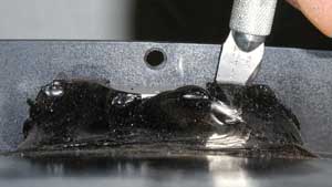
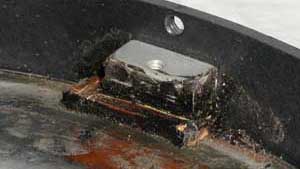
 A second mirror mounting scheme involves three thick RTV silicone pads that
have been squished between the rear of the mirror and three mirror
collimation brackets that attach to the forward screws of the previously
mentioned triangular pattern of screws on the rear of the tube. This is the
system used in my own Schmidt camera manufactured by Celestron in 1977. To
removed the mirror, the silicone has to be cut out with a razor blade or
Exacto knife, then the three brackets removed from the inside rear of the
tube to allow clearance for the mirror to be lifted out.
A third mirror mounting scheme found in Epoch built or modified cameras is a
silicone bead all the way around the mirror cell between the cell and the
tube assembly, with the silicone squished into the space between the cell
and tube. Again, the silicone has to be cut away to free the mirror.
When it came time to remove the mirror from my camera, the worrying about
taking it apart was far worse than the actual procedure of taking it apart.
Actually, disassembling the 8-inch Schmidt was rather easy. After marking
the tube where all the shims and corrector and mirror orientation went, I
pulled the mounting screws out of the collimation adjuster brackets and cut
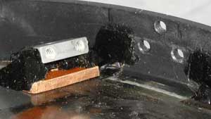
through the silicone with an Exacto knife. I found that buried inside each
silicone pad that glued the mirror in place was a ½ square inch spot of
Bakelite that acted as a pad between the mirror back and the collimation
adjusting screws. Once these were out and the silicone cleaned off the back
of the tube, the mirror fell right out. This emphasizes the need to perform
the mirror removal steps while the camera is nose down.
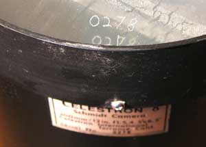
Before removing the mirror, engrave the camera's serial number on the back
of the mirror in line with the camera's serial number plate on the camera
body. This will allow aligning the mirror to its original position when it
is reinstalled.
A second mirror mounting scheme involves three thick RTV silicone pads that
have been squished between the rear of the mirror and three mirror
collimation brackets that attach to the forward screws of the previously
mentioned triangular pattern of screws on the rear of the tube. This is the
system used in my own Schmidt camera manufactured by Celestron in 1977. To
removed the mirror, the silicone has to be cut out with a razor blade or
Exacto knife, then the three brackets removed from the inside rear of the
tube to allow clearance for the mirror to be lifted out.
A third mirror mounting scheme found in Epoch built or modified cameras is a
silicone bead all the way around the mirror cell between the cell and the
tube assembly, with the silicone squished into the space between the cell
and tube. Again, the silicone has to be cut away to free the mirror.
When it came time to remove the mirror from my camera, the worrying about
taking it apart was far worse than the actual procedure of taking it apart.
Actually, disassembling the 8-inch Schmidt was rather easy. After marking
the tube where all the shims and corrector and mirror orientation went, I
pulled the mounting screws out of the collimation adjuster brackets and cut
through the silicone with an Exacto knife. I found that buried inside each
silicone pad that glued the mirror in place was a ½ square inch spot of
Bakelite that acted as a pad between the mirror back and the collimation
adjusting screws. Once these were out and the silicone cleaned off the back
of the tube, the mirror fell right out. This emphasizes the need to perform
the mirror removal steps while the camera is nose down.
Before removing the mirror, engrave the camera's serial number on the back
of the mirror in line with the camera's serial number plate on the camera
body. This will allow aligning the mirror to its original position when it
is reinstalled.
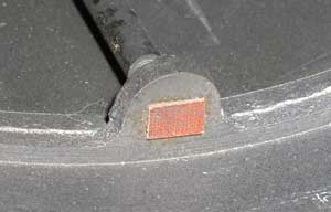
 On my camera, there was one cork shim about a half inch wide every 120
degrees around the rim of the mirror centering it in the cell. There was a
small 1/4-inch square spot of cork (very flattened) under the lip of the
cell where the Invar rods meet the face of the mirror. There is certainly no
effort to make any floatation support for the mirror. It is simply held into
its cell by being pushed into place with the three Bakelite pads under the
collimation jackscrews, then being siliconed in three places.
On my camera, there was one cork shim about a half inch wide every 120
degrees around the rim of the mirror centering it in the cell. There was a
small 1/4-inch square spot of cork (very flattened) under the lip of the
cell where the Invar rods meet the face of the mirror. There is certainly no
effort to make any floatation support for the mirror. It is simply held into
its cell by being pushed into place with the three Bakelite pads under the
collimation jackscrews, then being siliconed in three places.
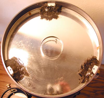
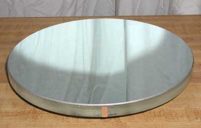 Wow! An 8-inch f/1.5 mirror is a deep bowl! For those who wondered, the
mirror is 8.75 inches in diameter and the cell masks it down to 8.5 inches
in diameter.
Most of the silicone holding the mirror can be cut or shaved away with a
razor or Exacto blade. But scraping away the final thin layer may also gouge
the metal of the camera body. A trick for cleaning off the residual silicone
from the back of the mirror and the inside of the tube is to rub it
vigorously with a coarse cloth or rag. Such a rag cleans silicone of an
object as surely as sandpaper cleans rust off metal.
Wow! An 8-inch f/1.5 mirror is a deep bowl! For those who wondered, the
mirror is 8.75 inches in diameter and the cell masks it down to 8.5 inches
in diameter.
Most of the silicone holding the mirror can be cut or shaved away with a
razor or Exacto blade. But scraping away the final thin layer may also gouge
the metal of the camera body. A trick for cleaning off the residual silicone
from the back of the mirror and the inside of the tube is to rub it
vigorously with a coarse cloth or rag. Such a rag cleans silicone of an
object as surely as sandpaper cleans rust off metal.
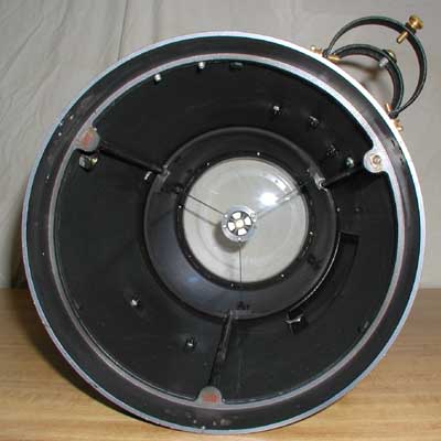
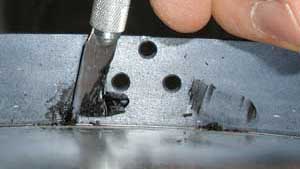
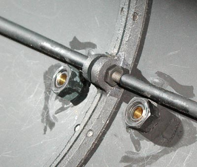
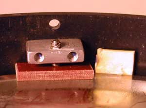
 The rim of the mirror cell is visible inside the tube. Note the cork pads
at the base of each Invar rod.
Once the mirror is removed the whole cell, Invar rod cage and spider can be
removed. If you remove this assembly, it is probable that when reassembled
the collimation and focus process will have to be performed. Because of the
inherent dificulties in aligning and focusing a Schmidt, I would advise
leaving the Invar cage in place unless some circumstance dictates it must be
removed.
The rim of the mirror cell is visible inside the tube. Note the cork pads
at the base of each Invar rod.
Once the mirror is removed the whole cell, Invar rod cage and spider can be
removed. If you remove this assembly, it is probable that when reassembled
the collimation and focus process will have to be performed. Because of the
inherent dificulties in aligning and focusing a Schmidt, I would advise
leaving the Invar cage in place unless some circumstance dictates it must be
removed.
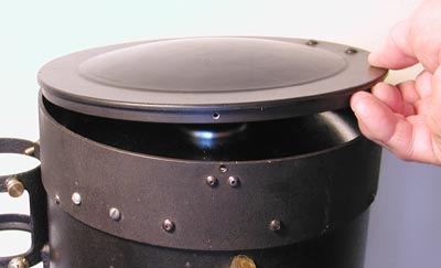
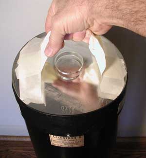 A "handle" made from several layers of masking tape can be used to lower the
mirror into its cell. There is no finger room between the mirror and tube so
this system allows inserting the mirror without having to drop it into the
cell. The previously engraved camera serial on the back of the mirror is
aligned with the camera's serial number plate to return the mirror to its
original position in the cell.
A "handle" made from several layers of masking tape can be used to lower the
mirror into its cell. There is no finger room between the mirror and tube so
this system allows inserting the mirror without having to drop it into the
cell. The previously engraved camera serial on the back of the mirror is
aligned with the camera's serial number plate to return the mirror to its
original position in the cell.
 The mirror installation is completed by attaching the collimation adjusted
backets. The final position of the mirror may change during the collimation
and focusing tests, so the mirror is not secured in position with silicone
until the camera is tested for collimation.
The mirror installation is completed by attaching the collimation adjusted
backets. The final position of the mirror may change during the collimation
and focusing tests, so the mirror is not secured in position with silicone
until the camera is tested for collimation.
Go to the previous page ---- Adjusting Camera Focus
Go to the next page -------- Modifications to the
Schmidt Camera