
In most cases, the camera can be disassembled and serviced without removing the corrector plate. However, if the interior of the tube assembly is to be repainted, corrector removal is mandatory. If at all possible, simply remove the corrector cell from the front of the tube while the corrector is still installed. The cell is held on the front of the tube by machine screws. If it is necessary to remove the corrector from its cell, it is vital to mark it so it is reinstalled with the proper surface facing outward and the plate is clocked to the original orientation within its cell. Accidentally loosing track of which side of the corrector is which can be a time consuming mistake. The variation of thickness on the corrector plate is only a few thousandths of an inch. You can't detect this with the eye. Most old household windowpanes have greater variation in thickness. (At least you can see the ripples in them) And don't think you can figure out which side of the corrector has the depression figured into it by pouring water on it and seeing where it puddles. This does not work because surface tension is too great between the glass and water, it just beads up. Make a note of the location of cork shims around the edge of the corrector. They keep the corrector centered. A good way to mark the corrector for proper orientation is to use a diamond glass scribe to mark the very edge of the corrector in the area normally covered by the retaining ring. This retainer comes off by removing the eight screws holding it in place. Various data related to the orientation of components can be scribed on the rim of the corrector as a permanent record for the instrument.
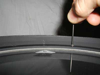 The corrector is marked with tape to aid alignment at reinstalation, then
the eight retaining ring screws are removed.
The corrector is marked with tape to aid alignment at reinstalation, then
the eight retaining ring screws are removed.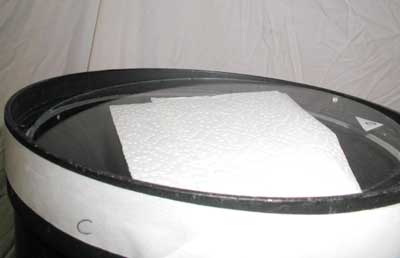 Several folds of paper towel protect the corrector when it is pushed out
by hand.
Several folds of paper towel protect the corrector when it is pushed out
by hand.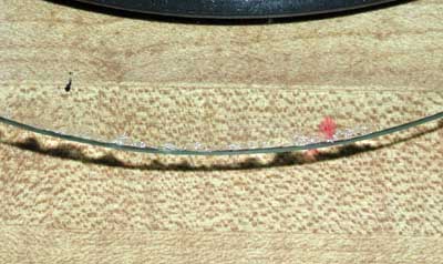 The corrector on my camera was chiped all the way around the rim of the
plate.
The corrector on my camera was chiped all the way around the rim of the
plate. Go to the previous page ---- Adjusting Corrector Plate Position